By Chander Kant Updated July 31, 2026
A compute cluster needs storage for several different purposes. The operating system and temporary files may remain on each node. User directories and software installations may need a shared namespace. Simulations, data analysis, and AI workloads may have to move large data sets through hundreds or thousands of processes at once. These uses do not place the same demands on a storage system, and they should not automatically be assigned to the same storage tier.
It is tempting to begin a storage design by adding drive capacities and interface speeds. Those numbers are important, but an application does not communicate directly with a collection of drives. Its I/O passes through a library, a file system, caches, a network, storage servers, volume management, and finally the media. Performance and reliability are properties of this complete path. A fast device at the end of a serialized metadata path can still produce a slow cluster.
This chapter follows that path from the compute node to shared storage. We will first examine local devices, RAID, volume management, and local file systems. We will then consider NFS and parallel file systems, using Lustre as a detailed example. The final sections connect these systems to MPI-IO and higher-level data formats, and describe how to test a storage design with the workload that will use it.
The storage path
Designing the storage path begins by deciding where a data set should live while the application is using it, and how far the bytes must travel between compute nodes and storage media. A cluster commonly presents several storage layers:
| Layer | Typical contents | Main design concern |
|---|---|---|
| Node-local storage | Operating system, temporary files, caches, and job-local scratch data. | Low latency and independence from the shared network, balanced against limited sharing and the loss of data when a node or device fails. |
| Shared project storage | Home directories, source code, software environments, and modest shared data sets. | A coherent namespace, permissions, reliability, and predictable metadata behavior. |
| Parallel scratch or campaign storage | Simulation output, checkpoints, training data, partitioned model weights, and large intermediate results. | Concurrent bandwidth and metadata capacity across many clients. |
| Repository or archive | Durable data sets, completed results, backups, and records that are retained longer than a job. | Integrity, lifecycle, recoverability, capacity cost, and time to retrieve the data. |
These layers describe roles, not mandatory products. A small cluster may provide several roles from one server. A larger installation may use local NVMe for temporary work, NFS for home directories, a parallel file system for active data, and an object or archival system for longer retention. The important point is to make the movement between layers explicit. If every job begins by copying a data set across the same narrow link, the copy phase is part of the storage design even when it occurs before the timed computation.
Block, file, and object access
Storage systems are also distinguished by the interface they present. A block device exposes numbered blocks and leaves the host to create a file system or another data structure on top. Local disks, logical volumes, and storage-area-network LUNs normally appear this way. A file service presents named files and directories together with operations such as open, read, write, rename, and permission checks. NFS and Lustre both present file-system interfaces, although their internal architectures differ greatly.
An object store presents objects in containers or buckets through a key or object identifier. Object interfaces often suit large data sets, repositories, and applications designed for them, but they do not natively provide the same operations as a POSIX file system. Appending within an object, renaming a directory tree, and coordinating writers may require the application or a gateway to perform additional work. Translation between interfaces does not remove those differences.
The interface matters because existing applications usually expect particular semantics. A program that opens one shared file from many MPI ranks needs a file system and I/O library that can coordinate those accesses. An application already organized around independent objects may avoid some namespace and locking work. Architecture should follow the data model instead of forcing all data through the interface associated with the newest device.
Node-local storage
Local storage is attached to one compute node and does not require a storage server or cluster network for ordinary access. That short path can provide useful latency and bandwidth, particularly with NVMe solid-state drives connected over PCI Express. Local storage can also isolate temporary I/O from the shared system. A job that spills data, sorts temporary records, or maintains a read cache may run faster without making every operation visible to all other nodes.
The same locality creates its principal limitation: another node cannot normally see the data. The scheduler or workflow system must arrange staging, and a replacement node may not have the files left on the original node. Unless the application maintains another copy, node-local scratch should be treated as temporary. Local RAID can protect against some device failures, but it does not make the data available after the node itself becomes unreachable.
Media and interfaces
Hard disk drives remain useful where capacity cost and sustained sequential transfer matter more than access latency. Solid-state drives remove mechanical seek time and can sustain far more random operations, but their performance depends on the controller, flash organization, queue depth, transfer size, write history, and endurance policy. Selecting an SSD therefore requires more than identifying the type of media.
SATA and SAS carry storage commands through interfaces derived from earlier disk designs. NVMe was designed for non-volatile memory and provides multiple hardware queues over PCI Express. A local NVMe device can remove interface bottlenecks that were hidden by rotating media. It can also move the bottleneck into the PCIe path, CPU, memory system, file system, or application. As with the interconnect in Chapter 3, the useful measurement is the application's observed path rather than the nominal rate of one link.
Linux exposes enough information to verify the path before benchmarking it. The following commands answer different questions:
lsblk -o NAME,MODEL,SIZE,ROTA,TYPE,FSTYPE,MOUNTPOINTS
nvme list
findmnt -T /path/used/by/the/job
iostat -xz 1This inventory prevents a surprising number of mistakes before measurement begins. It can reveal that a supposed local path is a network mount, that several names lead to the same underlying device, or that a test is running on a different mount than the one intended.
RAID and volume management
RAID combines several block devices to obtain capacity, performance, redundancy, or some mixture of the three. Linux software RAID, commonly managed with mdadm, performs this work in the operating system. Storage controllers and arrays can present a hardware-managed RAID set as one block device. Both approaches can be sound, but the operational details differ. The cluster administrator must know where device health, write caching, error reporting, rebuild policy, and spare management are controlled.
| Layout | What it provides | Principal tradeoff |
|---|---|---|
| RAID 0 | Stripes data across devices for combined capacity and throughput. | No redundancy. The loss of one member loses the array. |
| RAID 1 | Stores mirrored copies and can serve reads from more than one member. | Usable capacity is reduced by the number of copies. |
| RAID 5 | Stripes data and distributed parity while tolerating one failed member. | Small writes and rebuilds require parity work; a second failure is not tolerated. |
| RAID 6 | Adds a second parity calculation and tolerates two failed members. | More capacity and write work are devoted to parity. |
| RAID 10 | Stripes across mirrored pairs. | Uses substantial raw capacity but avoids parity updates. A rebuild places concentrated read load on the surviving member of a pair. |
A RAID level name does not completely describe an array. Device count, chunk size, stripe width, controller cache policy, workload size, and failure behavior all affect the result. A large sequential transfer may benefit from wide striping, while small synchronous writes can expose parity and durability costs. Rebuilds compete with applications for device bandwidth and may last long enough to become a normal operating condition on a large installation. Acceptance testing should therefore include a degraded array and a rebuild, not only a clean array.
RAID may preserve access after a device fails, but it does not recover a file deleted by a user, corrupted by software, or lost with the enclosure. The protection plan must identify independent failure domains and maintain recoverable copies where the value of the data requires them.
Linux shows the relationship between these layers through separate interfaces:
cat /proc/mdstat
mdadm --detail /dev/md0
pvs
vgs
lvs -a -o +devicesLogical Volume Manager
The Linux Logical Volume Manager adds an allocation layer above physical block devices. Devices become physical volumes, physical volumes are collected into a volume group, and space from that group is assigned to logical volumes. A file system sees a logical volume as a block device without needing to know exactly which physical extents supply it.
This indirection makes capacity changes, device replacement, snapshots, thin provisioning, and some RAID or cache arrangements easier to manage. With thin provisioning, physical blocks are assigned as data is written instead of being reserved for the full advertised size of every volume. The shared pool must be monitored because exhausting it can interrupt writes across several logical volumes. Snapshots also consume capacity as changed blocks accumulate, and a logical volume that spans failure domains can be only as reliable as the arrangement beneath it. LVM solves allocation and management problems; it does not replace a file system, backup, or high-availability design.
Local file systems
A local file system turns a block device into files, directories, allocation records, and recovery metadata. Ext4 and XFS are common Linux choices for cluster nodes and storage servers. Both are mature journaling file systems, and both can perform well when the geometry and workload are understood. The decision should be based on supported capacity, recovery procedures, administrative experience, and measured behavior rather than a universal claim that one is faster.
File-system geometry should agree with the storage beneath it. XFS, for example, records stripe-unit and stripe-width information so allocations can be aligned with a RAID or striped volume. Ext4 also has allocation controls related to stripe geometry. Misalignment can turn one application write into extra reads and writes across the array. Once the file system is in service, mount options and durability settings should be changed only with an understanding of the recovery semantics they alter.
Other local file systems may be appropriate when their particular features are required. Btrfs and OpenZFS provide checksumming, snapshots, and integrated storage-management capabilities through different implementations. Those capabilities can be valuable, but they introduce their own operational models. A compute node image, a scratch volume, and a storage server target do not necessarily need the same local file system.
Shared storage
A shared storage service gives more than one node access to the same data. Sharing a block device is not the same as sharing a file system. If two nodes mount the same writable block device using ordinary local file systems such as ext4 or XFS, they can issue uncoordinated allocation and metadata writes that corrupt the file system. Safe multi-node access requires a cluster file system, a distributed locking mechanism, or an application designed to coordinate direct block access. A storage-area network supplies block connectivity; it does not by itself supply a safe shared namespace.
Fibre Channel, iSCSI, and NVMe over Fabrics can all carry block access from hosts to storage systems. NVMe over Fabrics extends the NVMe command model across transports such as RDMA and TCP, rather than limiting it to a local PCIe attachment. These approaches differ in transport, management, performance, and operational practice, but the architectural question remains the same: which component owns allocation, locking, failure recovery, and the namespace? A database may coordinate direct access to raw or logical volumes. A general group of Linux clients normally needs a file service or clustered file system above the shared blocks.
NFS
NFS presents remote files through a familiar mounted namespace. It is often a practical choice for home directories, shared software, configuration, and workloads whose aggregate I/O fits the service. NFSv4 integrates facilities such as locking into the protocol and presents exported file systems through a server namespace. NFSv4.1 also defines parallel NFS, or pNFS, which can separate metadata access from direct access to multiple data servers.
A conventional NFS path still concentrates important work at the server or server pair. Its processors, memory, network links, backing storage, and metadata behavior place an upper bound on the service. Client caching can reduce traffic, but cache and consistency rules also affect what applications observe. NFS should therefore be judged with the intended number of clients, the intended mix of reads and writes, and the actual working set. A test from one warm client says little about a synchronized checkpoint from an entire cluster.
NFS works well in a compute cluster while the requested concurrency, bandwidth, metadata rate, and recovery behavior remain within the capacity of the service. Keeping home directories and software on NFS while directing large temporary results to a parallel file system is a common example of assigning different roles to different paths.
Parallel file systems
A parallel file system distributes the work of a file service across several components. The most important division is usually between metadata and file data. Metadata describes the namespace and the files within it: names, directories, ownership, permissions, timestamps, and the information needed to locate file contents. The contents themselves can be divided among several storage targets and moved by several storage servers at the same time.
This separation removes a data server from the path that need not be there. A client first obtains the metadata required to locate a file. It can then communicate with the storage servers that hold the file's data, instead of sending every byte through the metadata server. As more data targets and network paths are added, aggregate bandwidth can grow with them. Metadata capacity must be scaled separately because creating, opening, finding, and deleting files does not become cheaper merely because the data is spread over more disks.
Parallel file systems vary in how they place data, coordinate clients, recover from failures, and present their interfaces. Lustre and BeeGFS separate metadata services from storage services and allow clients to reach storage targets directly. IBM Storage Scale uses a clustered architecture with distributed coordination. CephFS presents a POSIX file system over Ceph's RADOS object store, with metadata served by a scalable group of metadata servers. Each provides a shared namespace, but the architectural choices lead to distinct hardware, network, and operational requirements.
Lustre
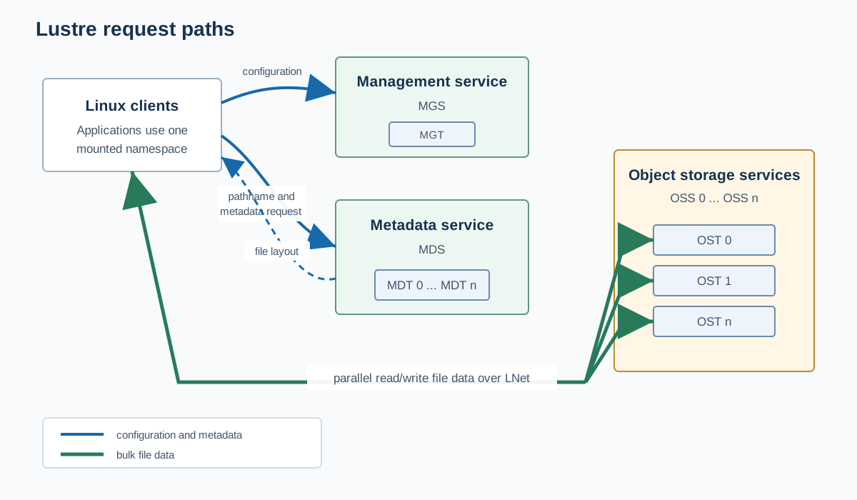
Lustre is an open-source parallel file system designed to provide a single POSIX namespace to many Linux clients. Applications use ordinary file and directory operations at the mount point. Behind that interface, Lustre separates the namespace from file contents and stripes file data across storage targets. This makes it possible for many clients, and even one client reading a wide enough file, to use several storage servers concurrently.
The terminology is easier to understand when services and storage targets are kept separate. A server runs a Lustre service; a target is the persistent storage that the service exports:
- Management Server and Management Target (MGS and MGT)
- The MGS provides configuration information used by the servers and clients of a Lustre file system. That information is stored on the MGT. The management service may share a host and storage with a metadata service in smaller installations, but its role remains distinct.
- Metadata Server and Metadata Target (MDS and MDT)
- The MDS serves one or more MDTs, although assigning distinct MDTs to separate active metadata services is the usual way to scale metadata work. It resolves names, checks permissions, creates file metadata, and records the layout that tells a client where the objects containing a file's data are located.
- Object Storage Server and Object Storage Target (OSS and OST)
- An OSS exports one or more OSTs. Each OST stores objects containing portions of file data. An OST commonly uses ldiskfs or OpenZFS on its underlying block storage, but clients see the combined Lustre namespace rather than those local target file systems.
- Lustre client
- The client is installed on a Linux node and mounts the Lustre file system. It communicates with the metadata and object storage services and presents the result through the Linux virtual file system.
- LNet
- Lustre Networking carries Lustre messages between clients and servers over configured network transports. Each endpoint has a Lustre network identifier, or NID, that combines its address with the LNet network. LNet can also route between Lustre networks. These transport and routing choices connect the storage design directly to the interconnect principles discussed in Chapter 3.
Following a file request
Consider a process that calls open() and then reads a region from a file. The Linux virtual file system passes these operations to the Lustre client module. The metadata client component resolves the pathname with the MDS and obtains the inode metadata and layout stored on the MDT. The layout identifies the OST objects that contain the requested portions of the file.
The object storage client component then sends data requests to the appropriate OSSs over LNet. Lustre's Distributed Lock Manager coordinates cached data and metadata among clients so that concurrent access follows the file system's consistency rules. The MDS remains responsible for namespace and layout work, but bulk file contents pass directly between the clients and the object storage services.
The two paths place different loads on the system. Opening millions of small files can be limited by metadata service work even when the OSTs are mostly idle. Reading several large, well-striped files can drive the object storage services and network while generating comparatively few metadata operations. A storage design needs separate estimates for data bandwidth, metadata operation rate, file count, and namespace growth.
File striping
A Lustre file can be divided into objects on several OSTs. The stripe count specifies how many targets participate, while the stripe size specifies how much contiguous data is placed on one target before the layout advances to the next stripe. The layout is chosen when the file is created. It can be set for an individual file or inherited from a directory default.
lfs getstripe /lustre/project/checkpoint.dat

# Set the default for new files created in this directory:
lfs setstripe -c 4 -S 4M /lustre/project/checkpoints

# Move an existing file to a different layout:
lfs migrate -c 8 -S 8M /lustre/project/checkpoint.datWider striping gives a large transfer more storage devices, controllers, and network paths from which to draw bandwidth. It also creates more objects and involves more targets in locking and I/O. A small file cannot usefully fill a wide stripe, and a workload that gives every file all available OSTs can spread overhead and contention across the entire system without gaining throughput. At the opposite extreme, placing a multi-terabyte shared checkpoint on one OST confines its data path to that target and its OSS. Stripe count and size should be selected for the file-size distribution and access pattern, then checked under concurrent load. A useful default for one application may be a poor default for the file system root.
Modern Lustre supports Progressive File Layouts (PFL), a form of composite layout in which different regions of a file use different layout components. An initial region can use one OST to limit the cost of a small file, while later regions use progressively wider stripes as the file grows. PFL can serve a mixture of file sizes without requiring the application to know the final size when the file is created, but its component boundaries and stripe widths still need to be matched to the workload.
Scaling the namespace
A Lustre file system begins with an MDT that contains the root of the namespace. Distributed Namespace Environment, or DNE, allows additional MDTs to contribute metadata capacity and performance while the client still sees one directory tree. Administrators can place directory subtrees on different MDTs, and a busy directory can be striped across several MDTs so that its entries are not all handled by one target.
Metadata distribution should follow measured namespace pressure. A workload that creates one large file per job needs little metadata work compared with a workflow that creates thousands of small files per rank. Directory striping can help the latter case, but it also distributes the work and state of that directory across more targets. The application may gain more by writing fewer, larger containers through HDF5 or PnetCDF than by asking the file system to absorb an unlimited file-per-rank design.
# Create a directory on a selected MDT:
lfs mkdir -i 1 /lustre/project/team-a

# Stripe one busy directory across four MDTs:
lfs mkdir -c 4 /lustre/project/shared-output

lfs getdirstripe /lustre/project/shared-outputReliability and operation
Lustre can be configured so another server takes over an MDT or OST when the active server fails. This requires a complete high-availability design: redundant access to target storage, network paths, fencing, resource management, and tested failover procedures. File Level Redundancy (FLR) can maintain mirrors for selected files on different OSTs, but Lustre does not automatically replicate every target as a complete volume. RAID, storage replication, or another protection method must still be chosen beneath the targets.
The distinction between MDT and OST failure is important. Loss of an OST affects the file objects stored on that target. Loss or corruption of critical metadata can affect the ability to locate far more data. Backups of configuration and metadata, target-level redundancy, and file-level recovery plans therefore answer different questions. Scratch data may justify a different balance of capacity and protection than home directories or irreplaceable results.
Operations also include compatibility and recovery, not only steady-state throughput. Lustre clients use kernel modules, and supported combinations of client kernels, Lustre releases, server software, and network drivers must be planned before Linux upgrades are rolled through the compute nodes. Monitoring should expose target free space, service availability, recovery state, network errors, and unusually slow requests. A benchmark result obtained while every target is healthy says nothing about how users will experience a full OST or a recovering server.
Other scale-out storage systems
Lustre is one implementation of a broader architectural idea, not the only route to parallel storage. The following systems are useful points of comparison:
| System | Primary interface and architecture | Question to examine |
|---|---|---|
| BeeGFS | A Linux parallel file system with separate metadata and storage services; clients contact storage services directly for striped file data. | How its service placement, metadata distribution, mirroring, and Linux client support fit the cluster. |
| IBM Storage Scale | A clustered file system, formerly known as GPFS, that can use direct shared storage or Network Shared Disk servers to provide concurrent file access. | How storage access, quorum, failure groups, licensing, and protocol services will be designed and operated. |
| CephFS | A POSIX file system over the RADOS distributed object store, with metadata handled by active and standby metadata servers. | Whether one Ceph platform serving file, block, and object roles is more valuable than a storage system focused on the HPC data path. |
| DAOS | A distributed object store with a native key-array-value model and interfaces for POSIX, MPI-IO, and HDF5. | Whether the applications can use its native or middleware interfaces and whether the deployment matches its storage and fabric requirements. |
A feature checklist cannot choose among these systems. The comparison has to include application interfaces, client operating systems, data and metadata patterns, failure domains, administrative staffing, upgrade policy, support model, and measured recovery. The storage system becomes part of the cluster's operating environment for many years, often outliving one generation of compute nodes.
Application I/O
A parallel file system creates several paths to storage, but the application determines whether those paths can be used effectively. Thousands of processes issuing small, unrelated writes may produce less useful bandwidth than a smaller number of coordinated processes issuing large transfers. The file layout, application request pattern, client cache, I/O library, and storage geometry meet at this point.
Four access patterns occur frequently in compute clusters:
| Access pattern | Advantage | Cost to examine |
|---|---|---|
| One file per process | Each process can write independently without coordinating offsets in a shared file. | File creation, directory contention, inode consumption, later discovery, and the cost of combining or moving many files. |
| One shared file with independent I/O | The result has one namespace entry and can preserve a convenient global layout. | Many small or interleaved requests, lock contention, and the need to keep process regions from overlapping incorrectly. |
| One shared file with collective I/O | Processes describe their requests together so an I/O library can combine them into larger, better ordered transfers. | Collective coordination, temporary buffering, and the need for all participating processes to call collective operations correctly. |
| I/O through aggregators | A subset of processes gathers data and issues storage requests on behalf of the others. | Extra communication and memory use, balanced against fewer storage clients and larger requests. |
File-per-process output is often the simplest implementation, and it can perform well when each file is substantial and directories are distributed. It becomes troublesome when process counts turn every checkpoint into millions of small files. A single shared file avoids that namespace growth, but independent writes can still reach the storage system as small noncontiguous requests. Collective I/O and explicit aggregators address this problem by reorganizing data before it reaches the file system.
MPI-IO
MPI-IO is the parallel file I/O interface defined by the MPI standard. A group of processes opens a file with an MPI communicator. Each process can describe the portion of the file visible to it through a file view, and can access that view with explicit offsets, individual file pointers, or a shared file pointer. MPI-IO supplies blocking and nonblocking operations as well as independent and collective forms.
The distinction between independent and collective access is especially important. An independent call involves only the process making the call. A collective call is made by all processes in the file's group and gives the implementation a global description of their requests. The implementation can then combine scattered regions into a smaller number of large, contiguous operations. This technique is often called collective buffering or two-phase I/O. For a write, processes exchange data with selected aggregators before those aggregators write to storage. For a read, the aggregators fetch contiguous regions from storage and distribute the requested portions to the processes.
Collective I/O is not automatically faster. Its communication and buffering cost may exceed the benefit when each process already issues a large aligned request. It becomes valuable when the application presents many small, interleaved, or noncontiguous requests that the file system would otherwise handle separately. The choice must be measured with the process count, file view, stripe layout, and MPI implementation used by the application.
ROMIO
ROMIO is a portable implementation of MPI-IO developed at Argonne National Laboratory and included with MPICH. It translates the standard MPI-IO calls through an abstract device interface to the operations available from the underlying file system. ROMIO can also apply optimizations such as collective buffering and data sieving, in which one larger region is transferred to satisfy several noncontiguous accesses.
The application should normally program to MPI-IO rather than to ROMIO-specific behavior. MPI distributions can provide different I/O components: current MPICH uses ROMIO, while current Open MPI releases use OMPIO. File-system hints and collective-buffering controls also differ among implementations. MPI permits an implementation to ignore unsupported hints, so an application can use MPI_File_get_info to inspect the settings retained for an open file. A tuning hint is useful only after the program's access pattern is correct and the active implementation has accepted it.
HDF5 and PnetCDF
Most scientific applications need more structure than a byte range in a file. HDF5 organizes multidimensional data sets, groups, attributes, and types in a portable file format. A Parallel HDF5 build uses an MPI communicator and the MPI-IO file driver so processes can access one HDF5 file. Some metadata operations must be collective. Data set transfers are independent by default and must be requested as collective through the data set transfer property list, using H5Pset_dxpl_mpio with H5FD_MPIO_COLLECTIVE.
PnetCDF provides direct parallel access to the classic NetCDF formats, including CDF-1, CDF-2, and CDF-5, and requires an MPI implementation with MPI-IO. NetCDF-4 uses HDF5 beneath its API instead. Both approaches let an application describe arrays and subarrays at a level above raw offsets. They can reduce the application code needed to maintain a portable data layout, but their chunking, metadata, and collective settings still affect the requests delivered to MPI-IO and the file system.
These libraries can also replace a large file-per-process collection with a smaller number of structured files. That change may greatly reduce metadata pressure, yet a single container can introduce its own coordination and recovery concerns. The useful design is the one that preserves the application's data model while producing transfers the storage system can serve efficiently.
Gauging storage requirements
Capacity is the first visible requirement, but active data, temporary data, replicas, snapshots, and retained checkpoints all consume different portions of it. The calculation should use usable capacity after RAID, mirroring, erasure coding, formatting, and reserved free space. It should also account for the rate at which old data is removed or moved to another tier. A scratch system without an enforced lifecycle eventually becomes an archive with scratch-level protection.
Bandwidth follows from the amount of data and the time available to move it. If a job must write a checkpoint of size D within time T, its minimum sustained application bandwidth is:
Bjob = D / T
For example, a 6 TB checkpoint that must complete in 300 seconds requires approximately 20 GB/s of sustained application write bandwidth. This is an application-visible requirement, not a sum of device data-sheet rates. If J jobs can checkpoint at once, a first estimate for the shared demand is J times the per-job rate. Protocol overhead, imbalance, metadata work, degraded components, and growth require additional margin. The concurrency policy of the scheduler can be part of the solution: staggering checkpoints may cost less than building every storage link for a synchronized worst case.
Metadata needs a separate estimate. Record expected file and directory counts, creates and deletes per second, open and stat rates, directory sizes, and the number of clients operating in one namespace. A system sized only for streaming bandwidth can fail its workload because a directory cannot absorb the creation rate. Conversely, a metadata-optimized all-flash design can be unnecessary for a workload that writes a few very large sequential files.
Latency matters where processes wait for small synchronous operations, where a model or data set must be loaded before useful work begins, and where metadata calls lie on the critical path. Aggregate bandwidth matters during scans, checkpoints, and large shared transfers. Tail latency matters when the next phase cannot begin until the slowest process completes. These measurements should remain separate instead of being reduced to one storage score.
Resilience, access, and lifecycle
The storage policy should state how long data must remain available, which failures it must survive, and how it can be reconstructed. Home directories, source code, active scratch data, model checkpoints, and final scientific results may deserve different answers. Snapshots can provide convenient point-in-time recovery, replication can preserve another online copy, and backups or archives can protect against failures that affect the primary system. None of these terms should be treated as interchangeable.
Access policy is a separate part of protection. POSIX ownership and permissions, access-control lists, project groups, NFS export policy, service credentials, and administrative access determine which users and services can reach the data. These boundaries need to remain consistent across storage tiers and during copies to repositories or archives.
Recovery objectives turn protection features into an operating design. Measure how long it takes to restore representative data, rebuild a target, fail a service over, and return the file system to normal performance. Document who can declare scratch data disposable and who verifies restored data. A protection mechanism that has never been exercised leaves its most important behavior unknown.
Test storage before accepting it
Storage tests should proceed from one device to the complete workload. Each stage isolates a different limit, and each result should record the hardware, software, mount options, file layout, client count, transfer size, working-set size, and cache state that produced it.
- Verify the path. Use
lsblk,findmnt, RAID and LVM tools, and file-system-specific commands to confirm which devices, mounts, targets, and networks the test will exercise. - Measure individual components. Use
fioor a vendor-supported device test to measure local media and block paths with representative read/write ratios, transfer sizes, queue depths, durability settings, and data verification. - Measure one file-system client. Establish sequential and random behavior for one client, using a working set large enough to distinguish storage performance from memory-cache performance.
- Add concurrent clients. Increase client and process counts while tracking aggregate bandwidth, per-client fairness, server CPU, network links, target utilization, and latency percentiles.
- Separate data and metadata tests. Use IOR for parallel data transfer and mdtest for file and directory operations. When the application uses several I/O layers, compare relevant IOR interfaces such as POSIX and MPI-IO to locate overhead. Test file-per-process, shared-file, flat-directory, and directory-tree patterns that resemble the applications.
- Run the application. Measure checkpoint time, restart time, data loading, useful compute time, and the I/O behavior of the actual HDF5, PnetCDF, MPI-IO, or framework build.
- Exercise full and degraded states. Test low-free-space thresholds, a failed device or server, rebuild, failover, recovery, and return to service. Confirm that monitoring identifies the condition before users do.
IOR and mdtest are useful because they drive parallel data and metadata paths through MPI. The IO500 suite combines several IOR and mdtest workloads under rules intended to make published results more comparable. These tools expose important limits, but their parameters can produce almost any story if they do not resemble the application. Report the command line and configuration with every result.
Caching deserves particular care. A short read of recently written data may measure client memory, server memory, or device cache rather than persistent media. A write may be acknowledged before every layer has committed it to stable storage, depending on the interface and requested semantics. Tests should use data volumes and durations that expose steady behavior, explicitly request the intended durability, and verify data from another client where shared visibility matters. Direct I/O can bypass the Linux page cache when that access mode is representative, but it has alignment and semantic constraints of its own. Clearing system-wide caches should be coordinated on dedicated test systems rather than performed on a production cluster merely to improve a benchmark.
Chapter 11's seismic imaging case study follows these choices through a complete workload. It shows how removing a serialized data path changed elapsed time and how the storage path interacts with memory capacity, the cluster interconnect, and accelerator utilization.
References and further reading
- NVM Express specifications
- Linux kernel documentation: RAID arrays
- Red Hat Enterprise Linux 10: Overview of logical volume management
- Linux kernel documentation: ext4
- Linux kernel documentation: XFS
- RFC 8881: Network File System Version 4 Minor Version 1
- Linux kernel documentation: pNFS SCSI layout server
- Lustre Operations Manual
- Lustre architecture for administrators
- Lustre file striping guide
- Lustre Progressive File Layouts
- Lustre File Level Redundancy
- BeeGFS architecture
- IBM Storage Scale overview
- CephFS documentation
- DAOS architecture
- MPI 5.0 standard
- MPICH source: ROMIO
- The HDF Group: Introduction to Parallel HDF5
- PnetCDF documentation
- fio documentation
- IOR and mdtest parallel I/O benchmarks
- IO500 submission rules